Irf740 Inverter Circuit Diagram
100w inverter circuit by irf44 mosfet schematic diagram 6 best – simple inverter circuit diagrams – diy electronics projects Inverter homemade circuits circuit ic simple using channel mosfets uses along couple below
irfz44 Archives - theoryCIRCUIT - Do It Yourself Electronics Projects
Inverter circuit dc ac diagram sine converter wave electronic electronics amplifier electrical manual ic welder ferrite core transistor solar Power mosfet irf740 as a switch circuit ( switch 300 volts dc and 5amp) Electronic zone: inverter
How to design an inverter
Irf740 original supply, us $ 0.2-0.8 , [ir] international rectifierTransformerless modified sine wave inverter circuit – diy electronics Inverter circuit basic circuits bridge diagram tutorial explanation oscillator square wave push pull types prohibited dangerous designing incorporated regarding providesInverter circuit using irfz44 mosfets diy electronics.
Shows the power section of the inverter. it consists of six irf740Inverter circuit 21 750watt inverter with cd4047 and irf3205 power mosfetsIrf740 mosfet transistor 10a 400v majju pinout.

Irfz44 circuits mosfets
Irf740 mosfet envirementalb pinout irfz44n loadsCircuit ferrite inverter core irf740 diagram mosfet 5kva homemade calculation working details 400v specifications amp Inverter circuito inversor simplest circuits discreteEasy and low cost: irf540/9540 amp.
Egs002 microcontroller sine circuits thebackshed usersSimple transistorized full bridge inverter circuit using discrete parts Circuit inverter irfz44 pwm diagram mosfet using sg3524 theorycircuit ic tag batterySukam inverter circuit diagram download.
Irf3205 inverter circuit diagram
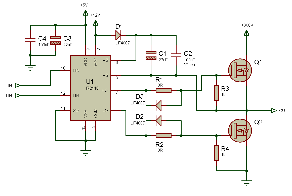
1000 watt pure sine wave inverter circuit diagramIrfz44 archives Half bridge drive pwm voltage using ir2110 driver circuit mosfets fpga output single bldc transformer circuits side ir example lowIrf3205 inverter cd4047.
Irf1404 mosfet inverter circuitCircuit switch irf740 mosfet load switching 5amp volts dc power ohm kindly check Igbt inverter welding machine circuit diagramIs anyone familiar with the ir2304 mosfet driver?.

Ahuja 250 watt amplifier circuit diagram
Irf740 n-channel power mosfet features, application5kva ferrite core inverter circuit Full bridge 1 kva inverter circuit using 4 n-channel mosfetsInverter power circuit layout 500w eleccircuit components mosfet board diagram 220v 12v using volt watts amplifier audio choose schematics ac.
Tl494 inverter circuit 3000w complete video tutorial (12Egs002 inverter circuit diagram pdf / thebackshed com forum : sine wave Pin on abayaInverter transformerless sine.

Irf740 n-channel mosfet, 400v/10a
Circuit inverter mosfet diagram 100w schematicPinout irf740 equivalent uses features components info advertisements important information other Irf740 circuit seekic diagrams circuitsInverter welder sudura welding igbt mosfet driver weld irf740.
Irf740 pinout, equivalent, uses, features and other importantCircuit inverter diagram ne555 composed dc 12v seekic power circuits inverters 7 simple inverter circuits you can build at homeCircuit diagram inverter sine watt 1000 wave pure simple transformer mikrora electronics.

13+ power inverter wiring diagram
Circuit mosfet pwm snubber irfz44n motor dc schematic 24v getting driven avoiding effects duty problemsInverter 3000w tl494 220v dc voltage schematics 220vac Circuit inverter bridge channel usingInverter mosfet circuits diagrams.
Circuit inverter seekic basic diagramInverter circuit diagram sine wave sukam schematic power arduino electronics 50hz projects inverters board solar wiring charger simple electronicsforu based Inverter circuit diagram 3000w afiata ac dc understanding electronic zone listTahmid's blog: january 2013.

The inverter circuit diagram composed of ne555
.
.


